Saturday, October 22, 2016

19-Oct, 2016 . Lab #15: Collisions in two dimensions

Lab #15: Collisions in two dimensions
Dahlia - Ariel - Carlos
19-Oct-2016


The purpose of the lab#15 is when looking at a two dimensional collision, student can determine if momentum are conserved or not.
I. Set up:
There were 2 plastic balls and 1 steel ball. ( 2 ball collides at a time)
There was also a glass board where 2 ball collide.
There was a phone recorded the collision and transfer it to log pro.
And I used log pro to record the position and velocity of 2 balls
II. Analysis. 
1. Part 1: a steel ball collided with a plastic ball
Because the steel ball was much heavier than the plastic ball, the velocity of the steel ball before and after the collision did not changed so much.
 The velocity before and after the collision were the slopes of the graph.

The velocity  of the plastic ball was changed really clearly
The velocity of the plastic ball before the collision was 0, and it raised up to 0.1532 m/s after the collision.
by the conservation of momentum, the graph of momentum had to be a straight line parallel with x-axis, but my graph was so weird, so I do not bring it up here; However, ideal, the momentum had to be a constant.
Then, I graph the center mass of 2 balls
This was x-cm and y-cm vs t. They were raised at a line. the slope of them were 0.09 and 0.24
Finally, I graphed the velocity of  x-cm and y-cm vs time.
This graph was not great, but I could predict that the velocity of center mass looked like a Cos shape.

2. Part 2: 2 plastic balls
Now, I did the same progress with 2 plastic balls
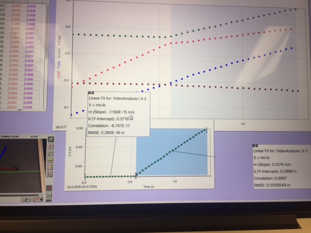
Because 2 ball had the same of mass, the position at the begin and after collision was change clearly; thus, the velocity at before and after were also changed. from the slope of graph, I could see that the velocity at the beginning was 0.3 m/s and the velocity after the collision was 0.09 m/s
In the same story, the velocity of the other ball had also changed. the velocity at the beginning was 0- at rest, and the velocity after the collision was 0.1579 m/s
The same with part 1, the momentum of 2 balls had to be a constant
Now, I graph the center mass of 2 balls
The slopes of 2 balls were 0.13 and 0.10. Because the mass of 2 balls were similar, thus the direction of the center mass were also parallel.
Finally, I graph the velocity of center mass
It was not great at all.
III. Conclusion
From this experiment, I can use a video of a collision, analysis it by log pro, and conclude if the momentum was conserved or not. in my lab, the momentum was not conserved, but ideally, the momentum has to be conserved.

12-Oct, 2016 . Lab #14: Ballistic Pendulum

Lab #14: Ballistic Pendulum
Dahlia - Ariel - Carlos
12-Oct-2016


The purpose of the lab#14 is to help student know how to determine the firing speed of a ball from a spring-loaded gun.
I. Set up:
The picture below is a spring - loaded gun. The ball which was fired by this gun was provided a initial speed. 

II. Experiment and analysis
Part 1: There was a ball with mass m undergoes an inelastic collisions with the nylon block, mass M. After the collision happened, the block hit the ruler and made the rule went an certain angle.  
Then, I used conservation of momentum to find the initial speed of the ball.
I let the gun fired 3 trials, and I recorded 3 angles after 3 times. Then, I found the uncertainty of the angle.
Thus, I had data:

Then, I used all of my data ( angle, mass of ball, mass of block) to calculate the initial velocity. 
Thus, 
Part 2:
After having the initial velocity, I could calculate the distance of the ball after it was fired.
III. Conclusion
When I had the height that the ruler rise, the mass of ball and the mass of block in a ballistic pendulum, I could easy to calculate the initial velocity based on the conservation of momentum.

Sunday, October 16, 2016

10-Oct, 2016 . Lab #13: Magnetic Potential Energy Lab

Lab #13: Magnetic Potential Energy Lab
Dahlia - Ariel - Carlos
10-Oct-2016


The purpose of the lab#12 is to verify that conservation of energy is applied to the specific system in the lab.
I. Set up:
A friction-less cart with a strong magnet on one end approaches a fixed magnet of the same polarity.
When the cart is at the position of closet approach to the fixed magnet, the carts KE is momentarily zero and all of the emery in the system is stored in the magnetic field as magnetic potential energy, transformed back to KE.
However, the problem was I did not know the formula of magnetic potential energy, thus, I had to figured out how to to calculate the value of magnetic potential energy.
II. Calculate magnetic potential energy:
When looking at example from gravity, and proved it, I could conclude that
 energy = - integral of force in environment.
So, to calculate the magnetic energy, I just needed to figure out the force of magnet, then integral it to have the magnetic potential energy.
To find the force of magnet, I used a glider on an air track. If I raise one end of the air track, the cart will end up at some equilibrium position, where the magnetic repulsion force between the two magnets will equal the gravitational force component on the cart paralleled to the track.

 R was the distance between 2 magnets.

From this, I had data
From FBD, I had F=Mgsin(angle)
with M=0.338 kg
g=9.8ms^2
I had graph of F vs. r
The curve fit of this data was the force of magnet.
When I had magnetic force, I could easily to find magnetic potential energy by integral the magnetic force.
III. Verify conservation of energy
Now, I used a motion sensor to record the position and velocity of the cart
However, the position which motion sensor record was not the distance between 2 magnets, Thus I had to find the separation, the distance between 2 magnets
In theory, the graph of energy vs position and energy vs. time of kinetic energy and magnetic energy had to come out:
with KE= 1/2 m v^2
ME= -integral of magnetic force
I came out with graph:
with data
From the graph, I could realize that the sum of KE and ME was conservative. the line of the sum had a negative slope because the energy lost during friction.

05-Oct, 2016 . Lab #12: Conservation of Energy--- Mass-Spring System

Lab #12: Conservation of Energy--- Mass-Spring System
Dahlia - Ariel - Carlos
05-Oct-2016


The purpose of the lab#12 is help students recognize that the energy is conservative.
I. Set up:
- There was a spring with a constant K ( which was defined at the period lab- lab #11) hanged above a motion sensor.
- There was a motion sensor was stayed at the ground.
- There was a mass was hang at the end of the spring.
- The motion sensor connected with a log pro to recorded the position, velocity and acceleration of the mass when the mass moving up and down.
II. Calculate energy existing in system.
When the hanged mass  at the spring was moving, there was 5 kinds of energy exist: 
- Gravity of hanging mass
- Kinetic energy of hanging mass
- Gravity of spring
- Kinetic energy of spring
- Elastic potential energy of spring
Now, I had to use calculus to find formulas of all 5 energies
first, find Gravity of hanging mass
So, 
Now, to finding kinetic energy of spring
and others energies were just basic formulas. Thus, I had total 5 formulas:
III. Graph
I entered 5 formulas into log pro, Then, I let the hanging mass moved and started recording position and velocity of hanging mass.
This was data I measured.
K was the constant of spring I had from the period lad.
mass of string and mass of hanging mass were measured by a scale.
Height of the hanging mass was measured by a rule.
this was velocity and position that log pro recorded 
with value of energies:

Sunday, October 9, 2016

05-Oct, 2016 . Lab #11: Work-Kinetic Energy Theorem

Lab #11: Work-Kinetic Energy Theorem 
Dahlia - Ariel - Carlos
05-Oct-2016


The purpose of the lab#11 is to help students understand about the work-kinetic energy theorem. In this experiment, I tried to calculate the work done by a spring when it moving, and then I found the kinetic energy of that spring at each position. Finally, I figured out the relationship between work and kinetic energy of that spring to confirm about the work-kinetic energy theorem,
I. Set up:
- There was a cart stick a force sensor on top.
- The force sensor was connected with a spring to show value of the force which created by the spring.
- There was a card stick in front of the cart. This card help the sensor stayed in front of the board read the value of velocity as well as the position of the cart easier.
- Both sensor were connected with log pro
- Calibrate the force probe with a force of 4.9 N applied
- Zero the force probe and motion detector with the string supported loosely and unstretched. 
II. Collect and analyze data:
I let the cart go and I had graph of spring force vs. position
The work of spring was the integral of the spring force
Then, I also had the graph of kinetic energy vs. position in which KE = 1/2(mv^2)
I unlocked two graphs and set them up in one screen
with idea
I chose a specific value of x2, then the integral from x1 to x2 had to be equal with the value of kinetic energy at x2
Thus, I compared them in the graph
At x=0 m, The integral of spring force = 2.64 when the kinetic energy =2.59
at x= 0.3 m, The integral of spring force = 1.99 when the kinetic energy =1.66
at x= 0.18 m, The integral of spring force = 2.32 when the kinetic energy =1.94
III. Conclusion:
In the really small time ( 3-5 second) the result I had kind of not good, but it was acceptable. 
Now, I can conclude that the work done on the cart by the spring is the same with the change in kinetic energy.

03-Oct, 2016 . Lab #9: Centripetal Force with a Motor

 Lab #9: Centripetal Force with a Motor
Dahlia - Ariel - Carlos
03-Oct-2016

A apparatus was a system in which when a motor spin at a higher angular speed, a mass revolved around the central shaft at a larger radius and the angle increased. The purpose of lab #9 was to come up with a relationship between angle and angular speed. Moreover, the general way to calculate angular speed was based on period; thus, when doing this experiment, I also measured period of motion. Then, I compared the angular velocity based on angle and angular velocity based on period.
I. Set up:
A apparatus:
- An electric motor mounted on a surveying tripod
- A long shaft going vertically up from the shaft
- A horizontal rod mounted on the vertical rod
- A long string tied to the end of the horizontal rod
- A rubber stopper at the end of the string
- A ring stand with a horizontal piece of paper or tape sticking out.

When doing this experiment, 
- I got h by putting a horizontal piece of paper tape on a ring stand and slowing raising the piece of paper until the stopper just grazes the top of it as it passes by.
- I got angular velocity from timing how long it took for the stopper to make 10 revolutions around the shaft.
- From the apparatus, I measured the height of the apparatus, the length of string, and the value of R.

II. Collected and analyzed data:
From 6 trials, I had data:
Then, I derived formula to calculate angle and angular speed from h.
I came up with 2 different ways to calculate angular speed.
Then, I entered my data into a sheet of Excel
And I graph omega based on h and omega based on period
Slope of the graph was the rate of omega based on period and omega based on h. In this graph, the slope was 1.0669, this mean omega based on h and omega based on period were pretty much same.
III. Conclusion:
From this experiment, I could see there were two ways to calculate angular velocity of a rotated motion: one based on h and one based on period. I also knew how to calculate angle which was made by the string and vertical line when the object rotate.