Sunday, November 27, 2016

21-Nov, 2016 . Lab #20: Conservation of linear and Angular Momentum

Lab #20: Conservation of linear and Angular Momentum
                                                                                                                 Dahlia - Carlos - Luis - Bimyia
21-Nov-2016


The purpose of the lab#19 is to confirm that the linear momentum and angular momentum are conservative.
In order to set up this lab, we need the Model ME-9821 Rotational Accessory Kit and the ME-9279A Rotational Dynamics Apparatus. We as students were not able to actually perform the lab ourselves so Professor Wolf is the one that demonstrated it to the whole class. 

I. Theory


because L = I.w
                 = m.r^2.v/r
                 = m.v.r
                 = p.r
Thus, to show the conservation of linear and angular momentum, we had to do 3 things. First, we had to calculate the angular momentum based on the moment of inertia and angular velocity. Then, we had to figure out the angular momentum based on linear momentum. And finally, we compared the both results.

II. Angular momentum based on linear momentum
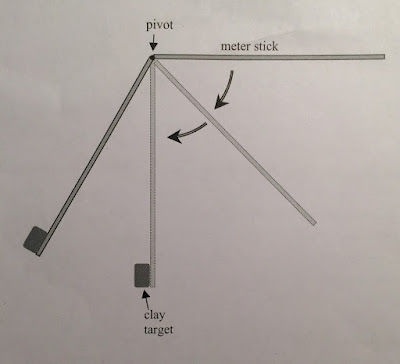
there was a ball slid down a ramp some height off the ground. Then it hit the ground at some point L away from the end of the ramp. And we had a piece of carbon copy paper was placed on the floor to find exactly where the ball hit. 


This was the actual value we had when measured distances.

Then, we figured out the velocity as well as measured the mass of the ball in order to calculate the linear momentum.

Because the angular momentum = mass of ball * velocity*radius from the axis. 
So, we could not calculate the angular momentum yet, but this was found later.

III. Angular momentum based on inertia and angular velocity
This part of the lab required the use of a rotational apparatus. The same ball would be launched from the ramp shown and caught by a little ball catcher attached to the top of a torque pulley on top of one of the rotating disks. 

Once the ball hit the ball catcher, the disk would begin to rotate. 

First, we had to find the moment of inertia. To find the moment of inertia, we needed to know the angular acceleration of the rotated object. Then, we used the formula from lab 16 to calculate the inertia momentum
the slope of the graph was the angular acceleration.
then, we had

Then, we let the ball run and found the angular velocity


Finally, we could calculate the angular momentum based on inertia and angular velocity. when doing this experience, we also know the radius from the axis. Therefore, we could calculate the angular momentum based on the linear momentum as well.

VI. Calculation and comparison
This was what we had

Now we could calculate the angular momentum
because we did 2 trials, so we had 2 angular momentums.
Then, we figured out the percent difference.
Linear M. inertia % diff.
Trial #1 0.00311 0.00246 23.3393178
Trial #2 0.00156 0.00174 -10.9090909
V. Conclusion
We already know that the linear momentum is conservative. now, according to this lab, we can assume that the angular momentum is also conservative. even though the percent difference of 2 ways to calculate the angular momentum are pretty high. this occurred because of some reasons such as the uncertainty of the radius from the axis, losing energy when the ball rotated as well as moved at the ramp, and the uncertainty when we measured the distances at the beginning. 

21-Nov, 2016 . Lab #19: Conservation of Energy/Conservation of Angular Momentum

Lab #19: Conservation of Energy/Conservation of Angular Momentum
                                                                                                                                          Dahlia - Carlos
21-Nov-2016

The purpose of the lab#19 is to confirm that the conservation of energy and conservation of angular momentum is true. In this lab, we release a meter stick, pivoted at or near one end, from a horizontal position. Right when the meter stick reaches the bottom of its swing it collides in-elastically with a blob of clay. The meter stick and clay continue to rotate to some final position. Like the picture:

Then, we calculated the height that the meter stick raised by using the conservation of energy and conservation of angular momentum as well as measured it from the experience. Finally, we compared them and concluded that the conservation of energy and conservation of angular momentum was still true or not.
I. Theory:
This was what we had, there was a meter stick rotated around pivot apart from 1 end 10 cm. 
Because the stick did not rotate around center of mass, so we had to calculate the inertia momentum around the pivot.
Then, we used the the conservation of energy to find the angular velocity of the stick before the collapse.
After that, we used the conservation of angular momentum to find the value of angular velocity after the collapse.
Finally, once again, we used the conservation of energy to figure out the height that the stick raised.
So, the theoretical data were: 
- Height of clay: 0.1356 m
- Height of center of mass of stick: 0.5603 m
II. Experience
After we had the theoretical data, we set up the meter stick and let it go.
 Then, we captured it and put it into log pro to measure the height that the stick raised.
So, the experimental data were: 
- Height of clay: 0.1411 m
- Height of center of mass of stick: 0.5898 m

III. Find percent error
I entered theoretical data as well as experimental data to a sheet of excel to find the percent error

  theory exp. %error
clay 0.1356 0.1411 4.05605
cm 0.560288 0.5989 6.89146

IV. Conclusion
Conservation of energy and conservation of angular momentum allowed us to calculate the angular velocity before the stick and clay collided.  We also used moments of inertia, the parallel axis theorem, and sum of individual components of GPE to calculate our theoretical value.  In the end, we had a 4.1% error with the raising of clay and 6.9% of the raising of the center of mass of stick. The error occurred because of some reason such as: Losing energy when the meter stick and clay stick together; Losing energy because of Air resistance; and the uncertainty of the original position when release the meter stick.

Saturday, November 19, 2016

14-Nov, 2016 . Lab #18: Moment of Inertia and Frictional Torque

Lab #18: Moment of Inertia and Frictional Torque
                                                                                                                                          Dahlia - Rafael
14-Nov-2016


The purpose of the lab#18 is to determine the time an object takes when it is connected with a rotated disk by a string in a given distance. And then, compared the time it takes by experimental value and theoretical value.
I. Theory:
To calculate the time, we had to have to know the acceleration of the object. To find it, we tried to figure out the angular acceleration of the disk.

So we had:
So, the angular acceleration of the disk depended on the radius of a small pulley, the mass of the cart, the angle of track, the inertia of the disk and the angular acceleration of friction.
And finally, we could calculate the time it takes 

II. Produce:
1. Inertia of the disk:
I=(1/2)*(mass of disk)*(radius of disk)^2
but the issue here was we did not know what the mass of the disk was; thus, we tried to figure out the mass of disk.
So, first, we measured dimensions of the disk-pulley.

Then, we calculated the mass of the disk.

And we came up with the mass of the disk was 4.18 kg.
Now, we could easy to calculate the inertia of the disk when it rotated around it center with mass = 4.18 kg and radius =0.1005 m
the inertia = 0.02092 kg*m^2
2. Angular acceleration of friction:
We recorded the rotated disk and put it in lab pro to figure out the angular acceleration of friction.
First, we marked a tape on the disk, then recorded every points of this tape.
Then, we pointed them in the log pro, and we get the graph of position vs. time

The log pro also provided the velocity of this tape vs. time.
So, we could have the angular velocity of this tape was velocity/radius
and the angular acceleration of friction was the slope of the graph angular velocity vs. time.
and it was 1.58 rad/s^2
Once again, I listed needed data to calculate the angular acceleration of disk.
Then, I found the time it took to travel 1 m with the angle 40 degrees.
The theoretical time was 11.276 s. 
3. Experimental value:
we set up the cart connected with the rotated disk by a string. This cart traveled in the track made 40 degrees with the horizontal. Then, we used timer to get the time this cart travel 1 m.

This was what we had after 3 trials:

4. Comparing the theoretical value with the experimental value:
I entered these data to a sheet of excel and calculate the percent error.

III. Conclusion:

 When Comparing  to the theoretical time vs the experimental time, the percent error came out only -0.67% error, and this was a really good result. 
Errors occur because of the friction between the carts wheels and the track. and the string not completely parallel with the inclined track. 
From now on, if we do not have a timer, and we need to find the time the cart takes in a  certain of distance, we can use the angular acceleration of the disk to know the needed time.

14-Nov, 2016 . Lab #17: Moment of Inertia of a Uniform Triangle

Lab #17: Moment of Inertia of a Uniform Triangle
                                                                                                                                          Dahlia - Rafael
14-Nov-2016


The purpose of the lab#17 is to determine the moment of inertia of a right triangular thin plate around its center of mass, for two perpendicular orientations of the triangle.
I. Theory:
The parallel axis theorem states that:
Because the limits of integration are simpler if we calculate the moment of inertia around a vertical end of the triangle, thus we can easy to calculate the inertia round center of mass based on the inertia about the vertical end.
The picture below shows how to calculate the inertia of uniform triangle around one end vertical as well as around it's center of mass.
First, I found center of mass of triangle. 
Then, I found the inertia when the triangle rotated around the edge and around the center of mass.

Thus, based on theory, the inertia of a triangle around center of mass is (1/18)*(mass of triangle)*(length of the horizontal edge)^2.
Moreover, there is another way to calculate the moment inertia based on Newton's second law and free body diagram.

Thus, the inertia of triangle around center of mass based on the mass of hanging mass, the radius of a rotation disk and the angular acceleration.


II. Procedure:
The pictures below are showing how we set up the kit when doing this experiment. Because this inertial is based on the angular acceleration, we did the same progress with lab #16 to get value of angular acceleration. we did three trials:
1 with the disks
1 with triangle horizontal larger side, 
and 1 with a triangle with horizontal smaller side.

This is what we had from the lab pro by sensor. The slope of the angular velocity vs. time was the angular acceleration.
So, after 3 trials, I had:

and this is the data of hanging mass as well as the radius of disk.
(from the lab #16.)
Therefore, hanging mass was 0.025 kg, and radius of the rotated disk was  0.0249 m.
Then, I measured dimensions of the triangle.

Then, I entered these value to a sheet of excel and from formulas, I calculated value of theoretical inertia based on rotation around the edge and value of experimental inertia based on angular acceleration.

and I calculated the percent error of them.

III. Conclusion:
By finding the difference between the moment of inertia of a rotating system and then the moment of inertia of a triangular plate mounted about its center in two positions, we were able to find the moments of inertia of the triangular plate itself.  Then, we calculated the moment of inertia about the triangular plate's edge using calculus, and plugged all of this into the equation for the parallel axis theorem to compare our mathematical results for moment of inertia about the triangle's center to our experimental results for moment of inertia about the triangle's center. 
The result came out was pretty good. The percent error was only within 2% at all 3 trials.
 Our errors in theoretical and experimental values could have been made from a number of factors: the mass of the triangular plate may not have been completely in uniform density; the air being released to spin the rotating disks may have fluctuated, causing acceleration to fluctuate; there also could have been error in the measurements.


Sunday, November 6, 2016

02-Nov, 2016 . Lab #16: Angular Acceleration

Lab #16: Angular Acceleration
                                                                                                                                          Dahlia - Carlos
02-Nov-2016


The purpose of the lab#14 is to to explore how angular acceleration changes when we use different hanging masses, rotating disks and combinations with different masses, and torque pulleys with different radii.
A. Part 1:
I. Set up:
The pictures below are showing how we set up the kit when doing this experiment.
From the side:
From the top:


There were a bottom steel disk, a top steel disk or top aluminum disk. they stayed next to the Pasco rotation sensor. 
At the top of disks, there was a small pulley or large puller which was connected with a hanging mass.
For this experiment we used an apparatus that provides a constant air pressure that kept the disks and hanging mass pulley "floating/hovering" so that we had friction-less for this experiment. 
The Pasco rotation sensor was connected with LabPro, so we could read value of angular position, angular velocity, and angular acceleration based on time.
II. Collect data:
1. Data of angular acceleration:
First, we turned on the constant air pressure and let the hanging mass started moving from the top of the string. And the disks also began rotating.
Next, we recording the movement. and this is what we had:
The first graph shows the relationship between angular position vs. time. And the second graph shows the relationship between angular velocity vs. time.
Because the purpose of this lab is to find the effects on acceleration of hanging mass, radius of pulley, and mass of rotating object, we paid attention to the graph angular velocity vs. time. (To find the angular acceleration, we just needed to find the slopes of the graph angular velocity vs. time)
Then, we had:
We did 6 trials of them, and this is what we had:

We used the caliber to measure diameters of top steel disk, bottom steel disk, top aluminium disk, small pulley and the large pulley. And we used a digital scale to measure the mass of top steel disk, bottom steel disk, top aluminium disk, small pulley, the large pulley, and the hanging mass supplied with the apparatus.
This is what we had:

From the trial #1, #2, and #3, We can conclude the effect of changing hanging mass.
Trial #1, hanging mass was 0.025 g, and the angular acceleration was 1.171 rad/s^2 (~1).
Trial #2, hanging mass was 0.050 g, and the angular acceleration was 2.298  rad/s^2 (~2).
Trial #3, hanging mass was 0.075 g, and the angular acceleration was 3.4245  rad/s^2(~3).
=> The angular acceleration was proportional with the hanging mass


From the trial #1 and #4, We can conclude the effect of changing the radius and which the hanging mass exerted a torque.
Trial #1, diameter of torque pulley was 0.0249 g, and the angular acceleration was 1.171 rad/s^2 (~1).
Trial #4, diameter of torque pulley was 0.0498 g, and the angular acceleration was 2.2235 rad/s^2 (~2).
=> The angular acceleration was proportional with the diameter of torque pulley.

Trial #4, rotation mass was 1356 g (~3*450), and the angular acceleration was 2.2235 rad/s^2 (~2).
Trial #5, rotation mass was 467 g  (~1*450), and the angular acceleration was 6.2845 rad/s^2 (~6).
Trial #6, rotation mass was 1356+1348=2704 g (~6*450), and the angular acceleration was 1.124 rad/s^2 (~1).


 By various changing in the hanging mass, radius of pulley, and rotation mass, we can conclude that the angular acceleration was proportional with the hanging mass, the radius of torque pulley, but the angular acceleration was inverse proportional with the rotation mass.
B. Part 2:
We can use our data collected and measurements to calculate moment of inertia for the system.  We used Newton's second law to find the tension, T, in the hanging mass.  We also used the equation for torque and plugged in tension to this equation (also changing linear acceleration to angular acceleration):
Then we had:


This equation was the way to calculate the inertia based on the angular acceleration we got from part 1. So, I entered data of part 1 into a sheet of excel, and then I calculated the experimental inertia. Moreover, because the disks were solid and rotated around center, so the theoretical inertia was 1/2MR^2. I calculated the theoretical inertial in the same excel sheet as well. 
To be more clear, I listed 2 ways to calculate the inertia:
Then, I calculated the percent error of them
Conclusion: The result came out was pretty good. the highest percent error was -3.35% and the lowest was 0.85%. The error occurred because of several reasons: first, because we assumed that the torque of friction was the same in all directions and independent of angular velocity, but in reality, it was not.Second, we assumed the disks were solid and apply I=1/2MR^2, but actually, it had a little hole at the center. And finally, when we recorded the angular acceleration from log pro, there were many up-down graph of it, so there was an uncertainty when taking value of angular acceleration. However, other than that, the result was really good and now, we can realize the amazing of physic to the real life.